Dry standard at this time of the year should be 8 to 11% at the highest. Don’t find the wood required until the last moment because (insert your home supply store name here) hardly ever has a truly dry piece of wood regardless of if it’s marked “Kiln Dried”. I have found 30+% in the middle multiple times when 3” from either end is 8.5%. Sometimes you can find something that’s been around the shop for quite a while that will work.
MATERIALS (STEP 1)
2
2x4x10 for sides – Please ensure they run true with no warping, racking or twisting.
1
2”x4”x8 for the ends – Please ensure they run true with no warping, racking or twisting.
3
Kiln Dried 2”x4”x96” – Please take your moisture meter with you to your supply store and ensure that they are 8 to 10% EMC using the Relative setting at 3” from each end and in the middle. If you can get relatively dry 2×4′, please install the screw at 3” from either end and in the center of the member to confirm. Failing to do this has resulted in weird demos several times. Most lumber is not really dried to 8-10% EMC. We need wood that is for this demo.
1 LB BOX
3 or 3.5” Stainless Steel uncoated Screws + Extra Drill Bits that match the above screws.
1 PK
12” to 16” Alligator Clips
10
Omnisense s-11 Sensors (let me know if you do not have in your inventory).
1
Omnisense Gateway – (let me know if you do not have in your inventory).
3 PK
Plastic Door Shims.
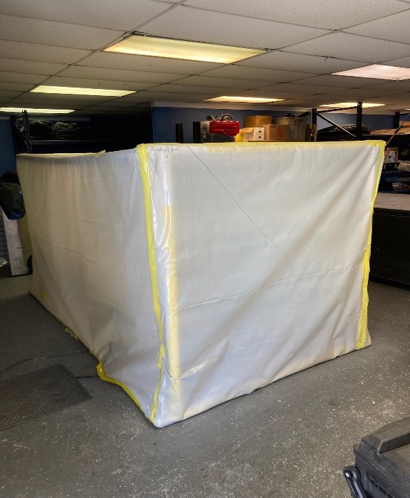
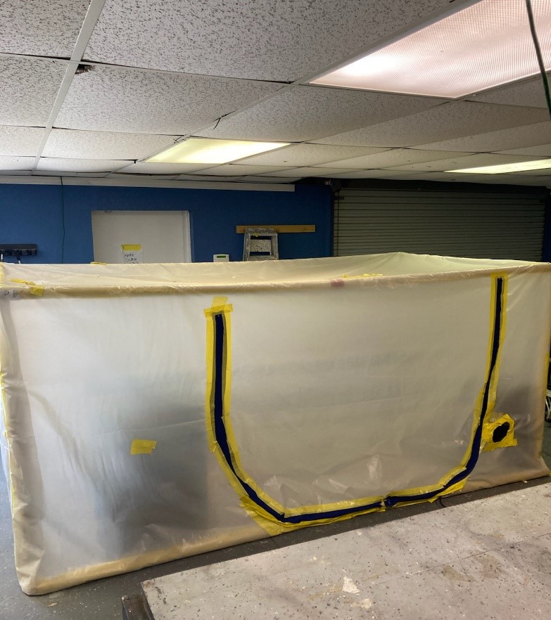
CREATING DRYING CHAMBER (STEP 2)
Frame Enclosure – 4’x4’x10′
Install Zipper
Please note 2 zippers opening from the center for access to interior.
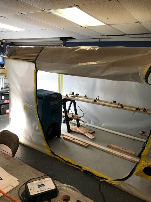
Add 2 Sawhorses inside the containment to hold the 8’ 2×4’s
Add a Dehumidifier to the Drying Chamber
CREATING WETTING CHAMBER (STEP 3)
a) Use (2) – 2”x4”x120” for the sides and (2) – 2”x4”X30” for the ends.
b) Line the chambers with 6 Mil Poly, ensuring you do not cut the poly as it needs to hold water and you don’t want another water loss….
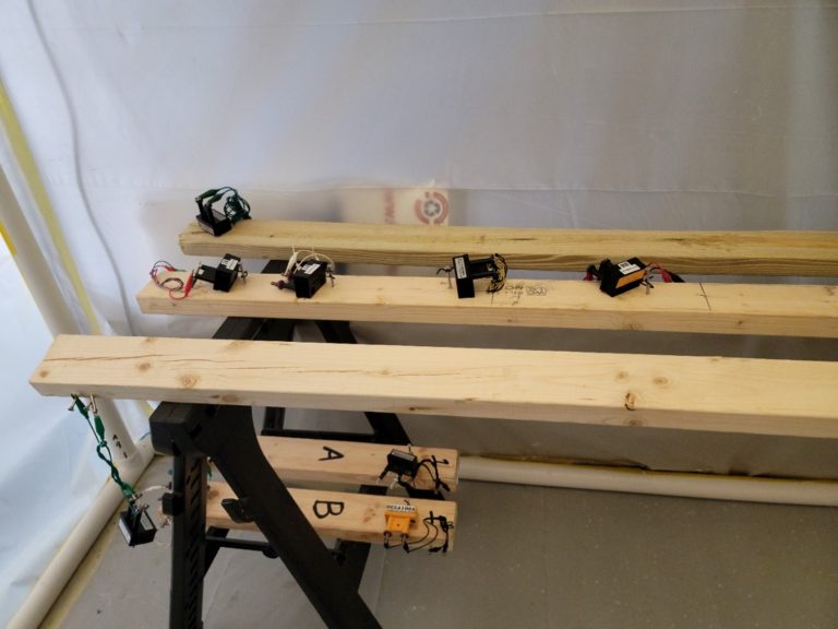
PREPARING YOUR WOOD MEMBERS (STEP 4)
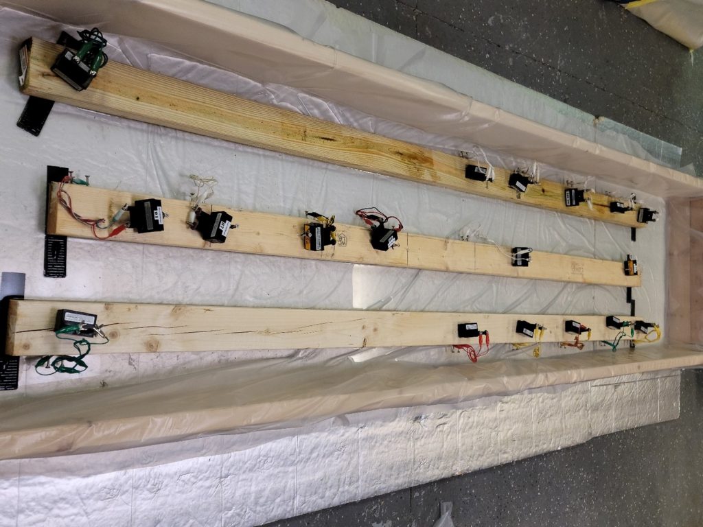
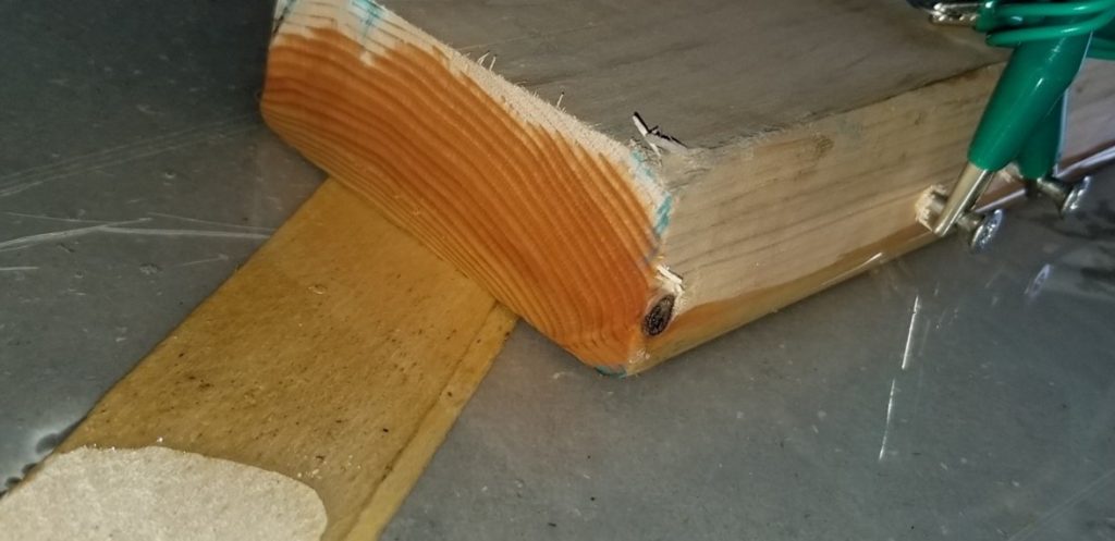
c) Find several 2”x4”x96” Kiln dried members and place (2) 3” uncoated Stainless Steel screw in the 2”x4”.
b) Place the screws midline in the 1.5” side of the 2”x4”’s parallel to the ground and approximately the distance apart of whichever Penetrating meter you are using has its penetrating probes spaced for easy survey later on.
a) Place the screws according to the supplied diagram as follows:
i) 3” from both ends
ii) 1’ from either end
iii) 2’ from either end
iv) 3’ from either end and
v) In the center at 4’ from either end
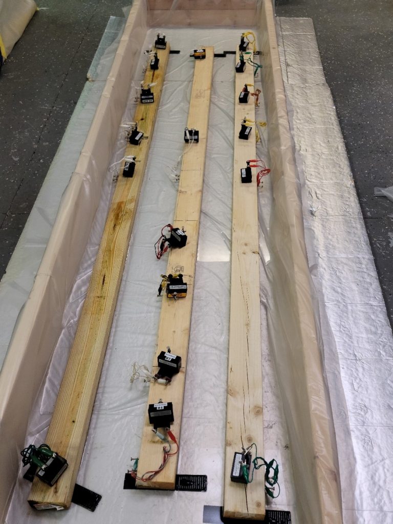
Positioning the members in the wetting chamber
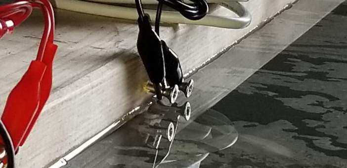
Place the 2’x4” members in the wetting chamber and shim all members level
When the water is added, we will need all of the members at the same level so the same amount of the wood on EACH member is wetted. As we will have screws centered on the 1.5” face of the 2×4, we can add not more than 3/8” to ½” of water to the Wetting Chamber so the water does not touch the screw or screw head. As there are screw heads approximately ½”from the ground, getting these members level is VERY important! Do your best in setup and we can adjust shims as necessary in the demo.